KUKA youBot Mobile Manipulation
The goal of this project is to showcase the fundamentals of robotic manipulation having the KUKA youBot move to pick up a cube from a known location and place it at another. The project plans a trajectory for the end-effector, arm, and chassis of the robot and uses a PI control loop with odometry to have the robot correctly complete the task.
Video Demo
Reference Trajectory Generation
To create the motion of the robot, I created the end-effector trajectory consisting of 8 distinct trajectory segments:
- Move the gripper from its initial configuration to a “standoff” position above the cube.
- Move the gripper down to a grasping position from the cube.
- Close the gripper to grasp the cube.
- Return to the first “standoff” position now holding the cube.
- Move to the “standoff” position above the final position of the cube.
- Move the gripper down to place the cube on the ground.
- Release the cube from the gripper.
- Return to the final “standoff” position above the cube.
As a part of this challenge, I created two unique trajectories with different initial and final placements of the cube to show robustness of the control of the robot.
youBot Kinematics Simulation
To calculate the kinematics and simulate the manipulation of the robot, I wrote two main functions. The first function uses simple Euler integration to calculate the next state of the robot chassis, arm, and wheel joints using the following inputs:
- The current configuration of the robot
- The current joint velocities
- The maximum velocity for the joints
- The timestep for the calculations
This function then returns the configuration of the robot for the next timestep.
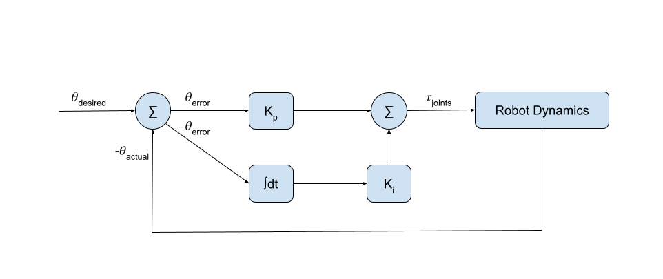
The second function I wrote serves as the control loop that ties the desired trajectory of the end effector to the actual motion of the end effector. A simple diagram of the control loop is seen below:

Feedforward Control
To calculate the control law, I calculated the current actual end-effector configuration X(q,θ) as a function of the chassis configuration q and the arm configuration θ. The values (q,θ) come directly from the kinematic simulation results (implying “perfect” sensors)
The output of this control yeilds the commanded end-effector twist expressed in the end-effector frame. To turn this into commanded wheel and arm joint speeds, I calculate the pseudoinverse of the mobile manipulator Jacobian Je(θ) to get the appropriate robot dynamics.
Joint Limiting Exploration
As a bonus activity, I explored adding joint limits to the youBot to simulate a more realistic scenario. In the CoppeliaSim program, the robot does not have limited joints, so the robot is able to cause collisions with itself if not constrained. To remedy this, I added a catch to evaluate whether the 3rd and 4th joints in the arm of the robot are greater than pi in the next state. If the condition yields true, then the joint positions and velocities are updated for the next state to ensure that they do not violate the constraint. Below is a video of the robot employing the joint constraints.
